How to Choose the Right Conveyor Roller for Your Needs?
Choosing the right Conveyors Roller is a practical engineering decision, not a simple catalogue search. Roller diameter, shell material, bearing design, load capacity, belt speed, and operating environment must work together. A roller that looks suitable in a warehouse may fail quickly beside abrasive dust, moisture, or frequent impact loading.
Industry data shows why this choice deserves attention. Grand View Research reports that the global conveyor systems market was valued at approximately USD 7.7 billion in 2022 and may grow at about 5.1% annually through 2030. CEMA’s Conveyor Equipment Manufacturers Association also stresses correct component selection, alignment, guarding, and maintenance in its conveyor standards. These findings suggest a clear lesson: a low purchase price does not always mean a low operating cost. Sometimes, it means the opposite.
Lawrence Nordell, founder of Conveyor Dynamics, has said, “A conveyor is a system, not a collection of components.” That principle applies directly to every Conveyors Roller specification. Consider a 108-millimeter steel roller under a heavy pallet line. Its bearings, shaft, seals, and spacing may matter as much as its rated load. Polyurethane may reduce noise, while galvanized steel may better resist damp conditions. Still, no guide can replace site testing. Conveyor layouts change. Dust behaves unpredictably. Even published ratings require careful interpretation.
This article explains how to compare roller types, calculate practical load requirements, and avoid common selection mistakes. It also examines maintenance access, energy use, noise, and lifecycle value, helping buyers choose with evidence rather than guesswork.
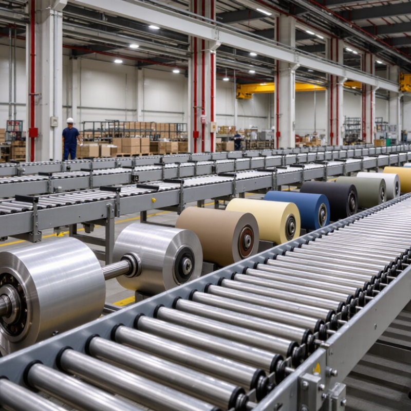
Define Load, Speed, and Throughput Requirements Using CEMA Rating Data
How to Choose the Right Conveyor Roller for Your Needs?
Selecting a conveyor roller begins with the actual load, not an estimated average. Measure the product weight, contact points, belt width, and load spacing. CEMA rating data helps compare roller capacity, shaft strength, bearing performance, and expected service conditions. Choose a rating above the calculated load, especially when packages land suddenly. Small errors matter. A roller carrying cartons smoothly may struggle with dense parts or uneven loading.
Speed and throughput must be evaluated together. Calculate the required units per minute, then check the roller’s recommended operating speed. Higher speed increases noise, vibration, bearing heat, and stopping distance. CEMA guidelines provide useful reference values, but they should not replace site measurements or supplier verification. I have seen clean calculations fail because the conveyor was exposed to dust, moisture, or frequent starts. Real installations rarely behave perfectly. Also, confirm the roller diameter and spacing prevent product sagging between supports.
Tips: Record the heaviest realistic load, not the typical one. Include impact, incline, temperature, and cleaning conditions. Compare calculated throughput with peak demand, then allow practical reserve capacity. Check shaft deflection and bearing life, not only the headline load rating. If the application is unusual, request documented test data and review the assumptions with a qualified conveyor engineer. A neat spreadsheet can still mislead. Measure the line again after installation.
How to Choose the Right Conveyor Roller for Your Needs? — Define Load, Speed, and Throughput Requirements Using CEMA Rating Data
Use the examples below as preliminary screening data for bulk-material belt conveyor idlers. CEMA class is a starting point, not a roller load rating: confirm the applicable CEMA standard, roller dimensions, bearing capacity, operating conditions, and manufacturer-published ratings before specifying equipment.
| Screening case | Belt width | Design capacity | Belt speed | Bulk density | Estimated material load | Example carrying-idler spacing | Material load per idler set | Initial CEMA class to evaluate |
| Light-duty, low-throughput service | 500 mm (20 in) | 72 t/h | 1.0 m/s | 800 kg/m³ | 20 kg/m | 1.0 m | 196 N (material only) | CEMA B or C, subject to duty and rating checks |
| Moderate-duty, general bulk handling | 650 mm (26 in) | 270 t/h | 1.5 m/s | 900 kg/m³ | 50 kg/m | 1.2 m | 589 N (material only) | CEMA C; evaluate D for harsher conditions |
| Heavy-duty, higher-throughput service | 800 mm (32 in) | 550 t/h | 2.0 m/s | 850 kg/m³ | 76 kg/m | 1.2 m | 894 N (material only) | CEMA D; check impact and service factors |
| High-capacity, severe-duty service | 1,000 mm (40 in) | 1,350 t/h | 2.5 m/s | 1,000 kg/m³ | 150 kg/m | 1.2 m | 1,766 N (material only) | CEMA D or E; verify calculated roller loads and speed limits |
Calculation notes
Estimated material load = throughput (t/h) ÷ [3.6 × belt speed (m/s)]. Material load per idler set = material load (kg/m) × idler spacing (m) × 9.81 m/s². Values are rounded and exclude belt weight, idler weight, impact, vibration, starting conditions, and uneven load distribution across rolls.
Select rollers using the actual calculated load on each roll, not the total load on an idler set alone. Check material lump size, loading-zone impact, trough angle, belt tension, temperature, moisture, contamination, bearing life, roller diameter, and rotational speed against the relevant CEMA data and equipment ratings.
Select Bearing Capacity with L10 Life and a Minimum Safety Factor of 1.5
How to Choose the Right Conveyor Roller for Your Needs?
Bearing capacity should begin with L10 life, not the roller’s maximum static rating. ISO 281 defines L10 as the operating life reached by 90% of identical bearings under the same conditions. This makes L10 a practical reliability benchmark. It is not a guarantee for every roller. Dust, impact, misalignment, and poor lubrication can shorten actual service life.
Measure the real load at each roller position. Include belt weight, material weight, transfer impact, and uneven loading. For example, a roller carrying 1,200 N should be selected with at least 1,800 N capacity when applying a 1.5 safety factor. The calculation is simple: required capacity equals working load multiplied by 1.5. Then verify the bearing’s L10 life at the actual speed and target operating hours. CEMA conveyor design guidance also emphasizes considering load distribution, belt tension, and loading conditions rather than using average load alone.
Small details matter. A 50 mm shaft can still fail if the bearing seat is misaligned. A sealed bearing may resist contamination, but it cannot correct excessive impact. A spreadsheet can look precise while missing a short, heavy load from a transfer point. I have seen designs pass paper calculations and struggle in dusty areas. Recheck the worst-case roller, not just the typical one. The 1.5 factor is a minimum safety margin, not permission to ignore field conditions.
How to Choose the Right Conveyor Roller for Your Needs?
Select bearing capacity with an L10 life target and a minimum safety factor of 1.5
Engineering example based on the ISO 281 basic rating life relationship for rolling bearings: L10 = (C/P)3. The minimum dynamic load rating is calculated as C = P × 101/3 × 1.5, using a target L10 life of 10 million revolutions and a minimum safety factor of 1.5. Choose a roller bearing whose rated capacity is at or above the calculated requirement.
Choose Roller Materials for Temperatures from −20°C to 80°C and Corrosion
Choosing a conveyor roller for temperatures from −20°C to 80°C requires more than checking load capacity.
Material selection affects friction, corrosion resistance, noise, and service life. Temperature changes matter.
Carbon steel rollers suit dry indoor areas when protected with paint or plating. However, a scratched coating can expose bare steel and create rust beneath the surface.
Stainless steel performs better in humid environments. Grade 304 handles general moisture, while grade 316 offers stronger resistance to salt and chloride exposure.
Polymer rollers resist many chemicals and reduce noise, but some plastics become brittle near −20°C or deform under continuous heat.
Seal and bearing choices are equally important. At low temperatures, grease may thicken and increase starting resistance. At 80°C, unsuitable seals can harden, swell, or lose their shape. Select lubricants and seals rated beyond the actual operating range. A small safety margin helps, especially near ovens, freezers, washdown zones, or outdoor loading areas.
In field inspections, I have seen rollers fail because only the tube material was considered. Moisture entered through a weak seal, and corrosion damaged the bearing within months.
Inspect pitting, discoloration, rough rotation, and metal flakes. Test a sample under real temperature, load, and cleaning conditions before wider installation.
Test before scaling.
Do not rely only on a material name. Ask for temperature ratings, corrosion data, load limits, and maintenance requirements. A polished specification can still miss your real working environment. Temperature, chemicals, cleaning frequency, and impact should be evaluated together.
Verify Spacing, Shaft Size, and Belt Width Against ISO 5048 Design Criteria
Choosing the right conveyor roller starts with the belt’s working conditions, not the roller catalogue. Verify belt width, material load, speed, and trough geometry before selecting dimensions. ISO 5048 provides a useful basis for checking belt tensions, resistance, and power requirements. These calculations help reveal the forces transferred to carrying and return rollers.
Roller spacing must support the loaded belt without excessive sag between stations. Closer spacing may be necessary near loading points, where impact forces rise sharply. Load changes. A practical check compares calculated belt tension with each roller station’s expected load. Then review the shaft diameter for bending, deflection, bearing capacity, and fatigue under continuous operation. A shaft that survives static loading may still fail after repeated cycles.
The roller face should suit the belt width and leave adequate edge clearance. Too narrow a face can damage belt edges; too wide a roller can add unnecessary mass and cost. ISO 5048 does not define every roller dimension, so use it with verified engineering data and applicable component standards.
Do not guess. Inspect actual loading, alignment, dust, moisture, and temperature at the installation site. A clean calculation can still miss a poor transition zone. Recheck the design after commissioning, because real material flow often differs from the original estimate.
 Skip to main content